Characteristics
The MO orifice flow meter measures the flow rate of fuel gas which is supplied to the burner. It is used to set the appropriate combustion capacity and air ratio.
MO orifice flow meter has 16 types ranging from 15A to 400A, and several types of orifice plates are available for each size.
| Type | MO-15 | MO-20 | MO-25 | MO-32 | MO-40 | MO-50 | MO-65 | MO-80 |
| Plate No. | [0A]~[8] | [08]~[11] | [08]~[14] | [06]~[17] | [05]~[18] | [02]~[21] | [10]~[24] | [10]~[26] |
| Type | MO-100 | MO-125 | MO-150 | MO-200 | MO-250 | MO-300 | MO-350 | MO-400 |
| Plate No. | [12]~[29] | [13]~[31] | [14]~[33] | [16]~[36] | [17]~[38] | [18]~[41] | [19]~[43] | [21]~[46] |
How to use
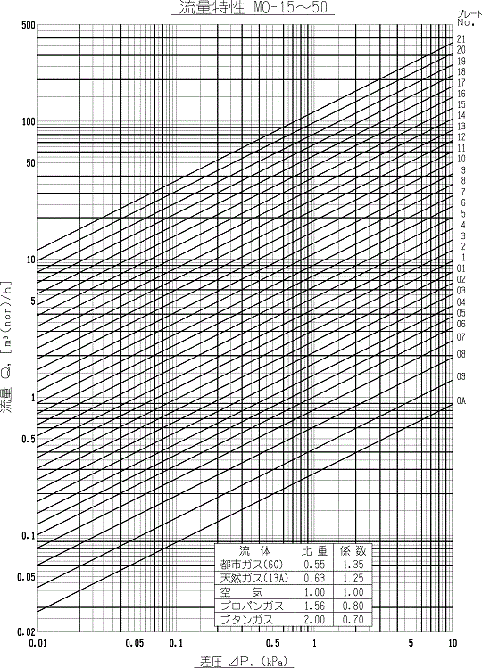
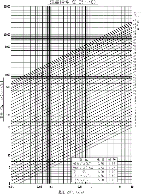
- Measure the differential pressure with a manometer or the like through the pressure sensing hole.
- Obtain the flow rate from the plate No. and the differential pressure by referring to the flow rate characteristic table.
- Multiply the correction coefficient according to the fluid type to obtain the true flow rate.
- Limit the operating temperature to under 50℃. (The flange type can be used at the operating temperature of fluid up to 500℃.)
- Limit the operating pressure to under 20kPa.
Caution
- Provide a straight pipe part of about 6 times as large in diameter as the pipe before and behind the orifice.
- Do not measure the flow rate when the differential pressure gauge indicates under 0.1kpa.
- When the orifice plate is replaced,be sure to replace the plate No. plate together.
- When a differential pressure type manometer is to be installed,contact our sales division for consultation.
- Be careful not to be wrong about the fluid inlet and outlet.
Precision
±2%(requirement 15℃)
Flow Rate
- Measure the differential pressure with a manometer or the like through the pressure sensing hole.
- Obtain the flow rate from the plate No. and the differential pressure by referring to the flow rate characteristic table.
- Multiply the correction coefficient according to the fluid type to obtain the true flow rate.
Outline drawing / Dimensions
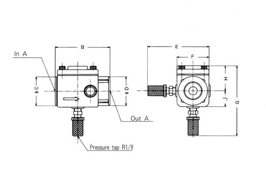
| Type | A(Rc) | B | C | D | E | F | G | H | J | Mass(kg) |
| MO-15 | 1/2 | 76 | 36 | 36 | 82 | 40 | 94 | 33 | 20 | 0.9 |
| MO-20 | 3/4 | 78 | 42 | 42 | 88 | 46 | 101 | 37 | 23 | 1.2 |
| MO-25 | 1 | 85 | 50 | 50 | 96 | 54 | 110 | 42 | 27 | 1.6 |
| MO-32 | 1 1/4 | 87 | 58 | 58 | 106 | 64 | 120 | 47 | 32 | 1.9 |
| MO-40 | 1 1/2 | 97 | 66 | 66 | 114 | 72 | 131 | 54 | 36 | 2.5 |
| MO-50 | 2 | 105 | 78 | 78 | 128 | 86 | 145 | 61 | 43 | 3.4 |
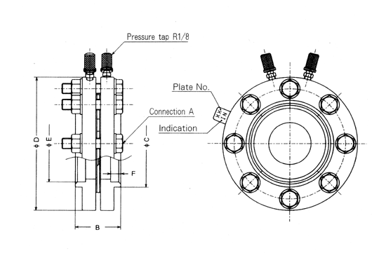
| Type | A(JIS5K) | B | C | D | E | F | Mass (kg) |
| MO-15F | 15A | 55 | 40 | 85 | 22 | 7 | 1.8 |
| MO-20F | 20A | 28 | |||||
| MO-25F | 25A | 56 | 47 | 95 | 35 | 2.1 | |
| MO-32F | 32A | 56 | 115 | 43.5 | 3.0 | ||
| MO-40F | 40A | 62 | 120 | 49 | 3.2 | ||
| MO-50F | 50A | 73 | 130 | 61 | 3.5 | ||
| MO-65F | 65A | 66 | 100 | 155 | 77 | 14 | 5.9 |
| MO-80F | 80A | 110 | 180 | 90 | 7.5 | ||
| MO-100F | 100A | 67 | 130 | 200 | 115 | 15 | 9.0 |
| MO-125F | 125A | 80 | 160 | 235 | 141 | 16 | 13.0 |
| MO-150F | 150A | 190 | 265 | 167 | 18 | 15.0 | |
| MO-200F | 200A | 81 | 238 | 320 | 218 | 20 | 20.0 |
| MO-250F | 250A | 99 | 295 | 385 | 269 | 25 | 33.0 |
| MO-300F | 300A | 350 | 430 | 321 | 38.0 | ||
| MO-350F | 350A | 109 | 385 | 480 | 357.5 | 49.0 | |
| MO-400F | 400A | 450 | 540 | 408.5 | 64.0 |
Download of DXF data
※ Download procedure
- Put the cursor on the model designation of the outline drawing you want to download, and click the right button of the mouse.
- Select “Save Target As (A)” on the menu.
- Select a location to save, and click “Save.”
※ Some security software does not permit downloading. If that happens, set the securities to “OFF” before downloading.
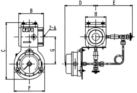
| Type | A(Rc) | B | C | D | E | F | G | H |
| MO-15-WO | 1/2 | 76 | 186 | 108 | 130 | 128 | 90 | 40 |
| MO-20-WO | 3/4 | 78 | 193 | 108 | 132 | 128 | 93 | 46 |
| MO-25-WO | 1 | 85 | 202 | 108 | 136 | 128 | 97 | 54 |
| MO-32-WO | 1 1/4 | 87 | 212 | 128 | 141 | 128 | 102 | 64 |
| MO-40-WO | 1 1/2 | 97 | 223 | 128 | 145 | 128 | 106 | 72 |
| MO-50-WO | 2 | 105 | 237 | 128 | 152 | 128 | 113 | 86 |
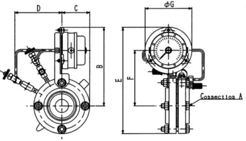
| Type | A(JIS5K) | B | C | D | E | F | G |
| MO-65F-WO | 65A | 220 | 78 | 130 | 298 | 155 | 130 |
| MO-80F-WO | 80A | 226 | 90 | 141 | 316 | 161 | |
| MO-100F-WO | 100A | 236 | 100 | 149 | 335 | 171 | |
| MO-125F-WO | 125A | 253 | 118 | 165 | 371 | 188 | |
| MO-150F-WO | 150A | 268 | 133 | 178 | 401 | 203 | |
| MO-200F-WO | 200A | 300 | 160 | 198 | 460 | 235 | |
| MO-250F-WO | 250A | 335 | 193 | 188 | 525 | 268 | |
| MO-300F-WO | 300A | 355 | 215 | 204 | 570 | 290 | |
| MO-350F-WO | 350A | 378 | 240 | 222 | 618 | 313 | |
| MO-400F-WO | 400A | 408 | 270 | 285 | 678 | 343 |
Characteristic