Characteristics
The controlling gas valve is integrated-the most suitable for proportional control by interlock with a pressure balance valve or other valves, or wide-range turndown.
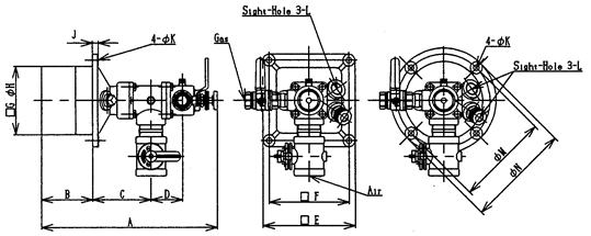
Specifications / Shape dimension
Specifications
| Fuel | Fuel Gases |
| Standard Pressure | Gas:2~10kPa Air:6kPa |
| Accessories | Butterfly Damper Gas valve |
| Type | Capacity kW (×1,000kcal/h) |
Air Flow Rate (Nm3/h) |
Connection | |
| Air | Gas | |||
| HNB-1/2 | 70(60) | 66 | Rc 1 1/2 | Rc 3/4 |
| HNB-1 | 147(126) | 139 | ||
| HNB-2 | 248(213) | 234 | RC 2 | Rc 1 |
| HNB-3 | 483(415) | 457 | RC 3 | Rc 1 1/4 |
| HNB-4 | 742(638) | 702 | RC 4 | Rc 1 1/2 |
| HNB-5 | 1,480(1,273) | 1,400 | 150A(JIS5K) | Rc 2 |
Dimension

| Type | A | B | C | D | E | F | G | H | J | K | L (G) | M | N | Mass (kg) |
|
| HNB-1/2 | 364 | 105 | 121 | 66 | 190 | 165 | □140 | Ø160 | 12 | 12 | 3/4 | 190 | 215 | 14 | |
| HNB-1 | |||||||||||||||
| HNB-2 | 439 | 130 | 141 | 81 | 230 | 200 | □170 | Ø190 | 14 | 230 | 260 | 22 | |||
| HNB-3 | 568 | 170 | 181 | 106 | 285 | 250 | □215 | Ø245 | 16 | 15 | 285 | 320 | 41 | ||
| HNB-4 | 707 | 220 | 221 | 131 | 350 | 310 | □270 | Ø305 | 18 | 1 | 355 | 395 | 77 | ||
| HNB-5 | 947 | 300 | 286 | 181 | 460 | 410 | □360 | Ø405 | 21 | 19 | 470 | 520 | 195 | ||
※ In placing an order for square tiles,affix “A” to the end of the model No.(Ex.HNB-1A)
※ In placing an order for round tiles,affix “R” to the end of the model No.(Ex.HNB-1R)
※ HNB-5 are flanged for connection to the air.
Download of DXF data
※ Download procedure
- Put the cursor on the model designation of the outline drawing you want to download, and click the right button of the mouse.
- Select “Save Target As (A)” on the menu.
- Select a location to save, and click “Save.”
※ Some security software does not permit downloading. If that happens, set the securities to “OFF” before downloading.
Combustion capacity table kW(×1,000kcal/h)
| Type | Air Pressure (kPa) | |||
| 0.06 | 6 | 0.06 | 6 | |
| Orifice No. | 1 | 2 | ||
| HNB-1/2 | 7(6) | 70(60) | 6(5) | 58(50) |
| HNB-1 | 15(13) | 147(126) | 12(10) | 116(100) |
| HNB-2 | 25(21) | 248(213) | 21(18) | 209(180) |
| HNB-3 | 48(42) | 483(415) | 41(35) | 407(350) |
| HNB-4 | 74(64) | 742(638) | 66(57) | 663(570) |
| HNB-5 | 148(127) | 1,480(1,273) | 128(110) | 1,280(1,100) |
| Type | Air Pressure (kPa) | |||
| 0.06 | 6 | 0.06 | 6 | |
| Orifice No. | 3 | 4 | ||
| HNB-1/2 | 5(4) | 47(40) | 3.5(3) | 35(30) |
| HNB-1 | 9(8) | 93(80) | 7(6) | 70(60) |
| HNB-2 | 19(16) | 186(160) | 16(14) | 163(140) |
| HNB-3 | 34(29) | 337(290) | 29(25) | 291(250) |
| HNB-4 | 58(50) | 580(500) | 50(43) | 500(430) |
| HNB-5 | 105(90) | 1047(900) | 81(70) | 814(700) |
※ Specify the orifice No. by referring to the fuel capacity table.
Flame Pattern

| Condition | |
| In the Air | |
| Air Pressure | 6kPa |
| Fuel | LPG |
| Excess Air Ratio | 1.1 |
| Type | ØD (mm) | L (mm) | L1 (mm) |
| HNB-1/2 | 120 | 400 | 105 |
| HNB-1 | 150 | 500 | 105 |
| HNB-2 | 180 | 720 | 130 |
| HNB-3 | 200 | 980 | 175 |
| HNB-4 | 260 | 1,300 | 220 |
| HNB-5 | 330 | 1,600 | 300 |